Moldavite Zen
home / moldavite geology origins / The Binary Impact Myth: Are Ries and Steinheim Actually Twins?

Deconstructing the Binary Impact Hypothesis: Stratigraphic Separation of Ries and Steinheim

Geologists have long operated under the assumption that the Nördlinger Ries and Steinheim Basin formed simultaneously via a synchronized asteroid pair.

Standing in the North Alpine Foreland Basin holding a rock hammer and a core sample presents a complex diagnostic challenge: confirming whether these craters represent contemporaneous structures or two independent kinetic events separated by roughly half a million years.

Conventional isotopic dating methods routinely failed to yield a geologically meaningful age for the smaller Steinheim structure, prompting practitioners to default to the synchronized model.

Bypassing standard radio-dating requires executing a high-resolution stratigraphic and seismic field analysis. This manual outlines the exact field-tested protocol to isolate the Ries and Steinheim events. You will achieve this through the inspection of continuous drill cores and the precise mapping of the seismite-ejecta couplet.
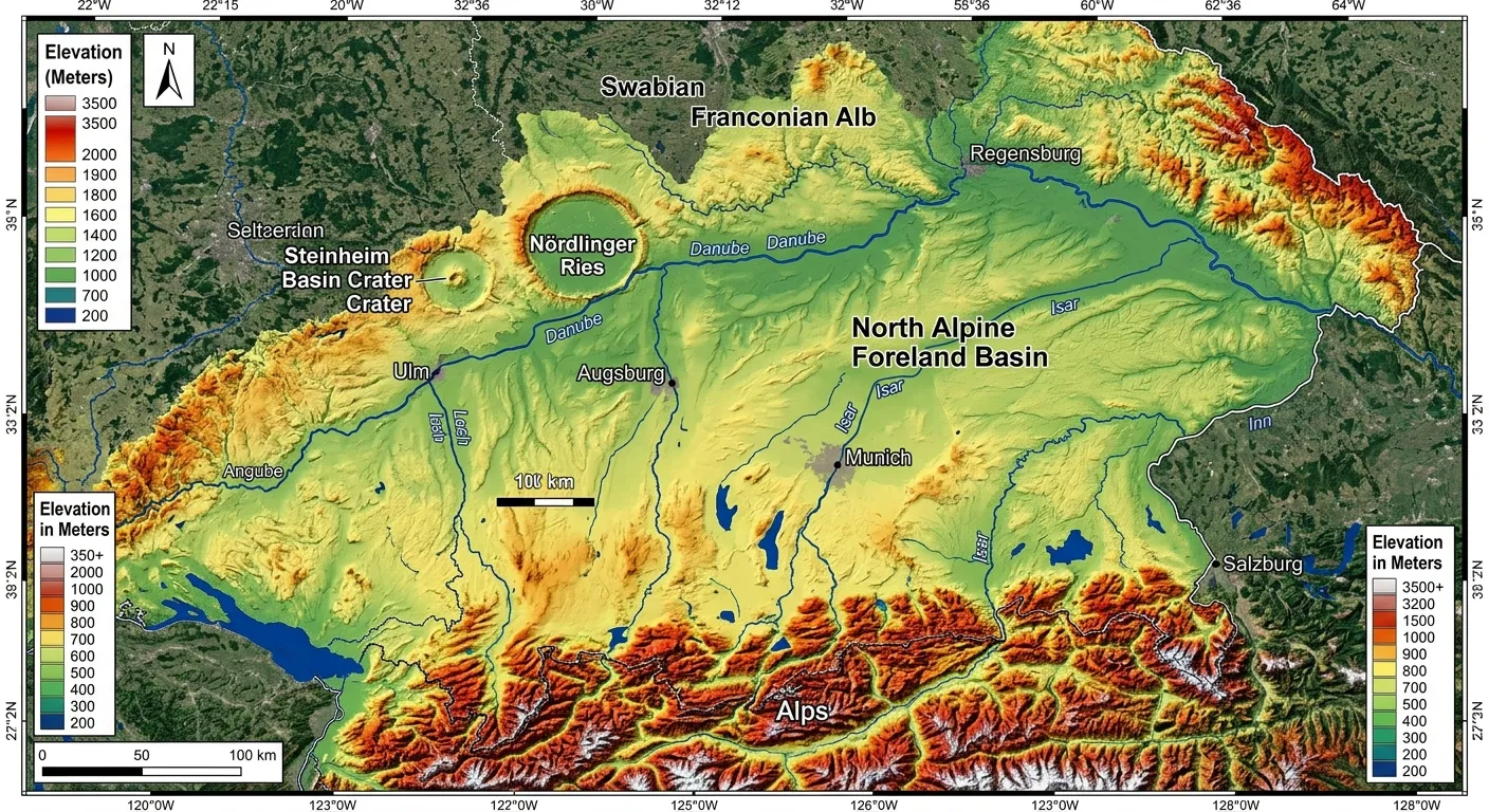
High-resolution digital elevation model of the North Alpine Foreland Basin
Digital Elevation Model highlighting the topographical anomalies of the North Alpine Foreland Basin.

⚙️ Tools Required & Field Arsenal

Assemble the precise tools required before navigating the ravines (Tobels) of Southern Germany. Leave hobbyist equipment behind; analyzing the Upper Freshwater Molasse demands strict instrumental tolerances.

Physical Hardware

  • Geological hammer (Estwing 22oz pointed tip).
  • Hand lens (10x and 20x triplet configurations).
  • Munsell Soil Color Chart (utilized to differentiate Molasse horizons).
  • GPS receiver maintaining sub-meter accuracy.

Analytical Software

  • Deploy a web-based computer program to calculate the atmospheric and seismic outputs, specifically designed to calculate the regional environmental consequences of bolide strikes (e.g., the Imperial College/Purdue Impact Earth simulator).
  • Petrographic microscope configured for shocked quartz grain optical verification.

Data Access

  • Secure institutional access to the continuous drill cores extracted during the 1970/1973 Ries research campaigns.
  • Faunal record databases cross-referencing European Land Mammal Zones (ELMZ).

Alternative Options

  1. Low-Cost Field Proxy: Apply the "Hydrochloric Acid Test" directly on the outcrop if mobile laboratory access is restricted. Distal Ries Ejecta (DREL) frequently contains Upper Jurassic limestone clasts; isolating these within the siliciclastic Molasse establishes an immediate, observable marker for the Ries horizon.
  2. Digital Proxy: Launch Google Earth Pro and overlay high-resolution DEM (Digital Elevation Model) data. Use this topography to deduce that the impact trajectory parallels the known ejecta distribution prior to initiating physical excavation.

🕹️ Step-by-Step Execution Protocol

Execute the following step-by-step workflow to systematically dismantle the synchronized impact model.

Step 1: Locating the Ries Seismite-Ejecta Couplet

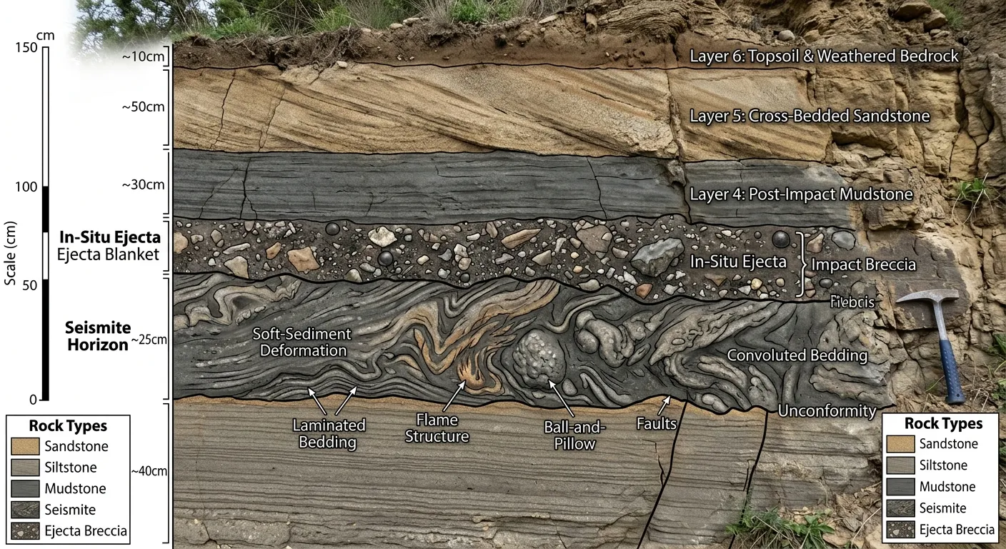
Your primary objective involves isolating the stratigraphic signature of the initial strike. Navigate to the North Alpine Foreland Basin, targeting exposures like Tobel Oelhalde-Nord, to locate a highly specific sequence: a seismite horizon capped immediately by in-situ ejecta.

  1. Identify the base Upper Freshwater Molasse (UFM) sequence.
  2. Scan the profile for soft-sediment deformation structures (SSDS). These manifest as slumped or severely folded layers trapped within horizontally bedded sands.
  3. Isolate the DREL (Distal Ries Ejecta Layer). Look for a "Brockhorizont" matrix holding boulders of Upper Jurassic limestone.
  4. Verify the structural couplet: If the ejecta layer rests directly atop the deformed horizon without intervening sedimentary deposits, you have successfully pinpointed the primary Ries impact boundary.
Stratigraphic profile showing a seismite horizon capped by in-situ ejecta
Visual verification of the seismite-ejecta couplet in the field.
Pro Tip: Scan the ejected cobbles for shatter cones. These structures indicate shock pressures exceeding 2 GPa. Finding them confirms an impact origin rather than a standard gravitational landslide.
If X happens, do Y: If the ejecta clasts display rounded edges or mix heavily with local fluvial pebbles, the deposit has revealed any sign of reworking. This indicates secondary transport, rendering it useless for precise chronological mapping. Relocate to a higher topographical elevation or a more distal ravine to locate the undisturbed in-situ layer.

Step 2: Identification of the "Steinheim Dikes"

This phase serves as the primary differentiator. Falsifying the synchronized model requires mapping structural evidence of a subsequent seismic event that triggered after the Ries ejecta settled.

  1. Scrape the outcrop face clean to expose the complete vertical succession.
  2. Scan for clastic dikes—vertical veins of injected sand or silt that cut through the Ries seismite-ejecta couplet.
  3. Trace the upward or downward trajectory of the dike. If the injected material penetrates the Ries layer from a stratigraphically higher position, the seismic trigger must postdate the Ries event.
  4. Measure the exact sediment thickness positioned between the Ries couplet and the origination point of the clastic dike.
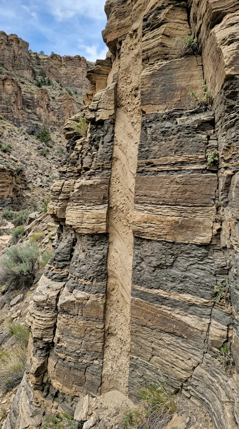
Vertical clastic dike cutting through older sedimentary layers
A distinct clastic dike severing the established baseline stratigraphy.
Pro Tip: Analyze the structural relationship mechanically. The older Ries layer represents the established baseline stratigraphy, while the clastic dikes represent a subsequent, independent kinetic event injecting material into the existing formation.
If X happens, do Y: If the clastic dikes remain visually obscured, spray the outcrop wall with water. Saturating the surface provides the necessary contrast to differentiate the host Molasse from the injected dike material. Apply this fix to immediately enhance visual clarity.

Step 3: Calculating Regional Environmental Consequences

Transition from physical fieldwork to digital modeling. You must assess the physical properties of both proposed impactors to determine the feasibility of a synchronized strike.

  1. Feed the established Ries parameters into your digital simulator: Diameter ~1.5 km, velocity ~20 km/s, target rock composition: crystalline basement beneath a sedimentary cover.
  2. Compute the resulting seismic magnitude. Industry models indicate a 24-km crater generates a magnitude 8.5 seismic event.
  3. Input the Steinheim bolide parameters: Diameter ~150m, final crater span ~4km. Computations generally output a magnitude 6.6 seismic event.
  4. Evaluate the maximum seismic reach. A magnitude 8.5 shockwave generates seismites up to 200km outward. A 6.6 shockwave possesses a drastically reduced radius. If clastic dikes manifest 100km from the Steinheim epicenter, the source must be modeled as a massive object to mathematically justify the observed kinetic energy transfer.
Acoustic & Seismic Energy Distribution
Pro Tip: Factor in the regional hydrogeology. If the target zone contained a shallow marine or lacustrine environment, the incoming bolide would first need to penetrate the water cavity wall, which drastically alters the subsequent acoustic and seismic energy distribution.
If X happens, do Y: If the generated seismic magnitudes fail to align with the physical deformation observed in the field, recalibrate the target rock variables. Unconsolidated Molasse sediments amplify seismic wave propagation significantly more than rigid granitic basements. Initiate standard troubleshooting protocols by adjusting the substrate density values in the software.

Step 4: High-Resolution Core Inspection

Field outcrops occasionally lack sufficient preservation. When this occurs, shift your focus to subsurface data.

  1. Submit a formal request for core repositories that crosscuts the entire succession of the Miocene Molasse basin.
  2. Scan the core logs for the "Ries Sonatas"—a rhythmic, undisturbed alternation of clay and sand denoting the pre-impact depositional environment.
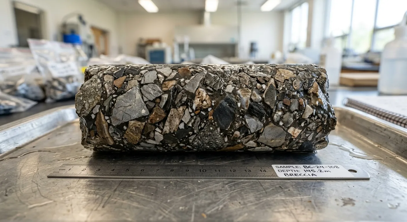
  3. Isolate the primary event layer. Within a confined core, the Ries impact signature typically manifests as an abrupt, chaotic influx of angular lithic fragments.
  4. Analyze the overlying sequence for a secondary liquefaction horizon or a distinct, later ejecta pulse. Identifying 10 to 20 meters of standard background sedimentation between two chaotic horizons provides mechanical proof of temporal separation.
Geological drill core sample showing chaotic lithic fragments
High-resolution core sample revealing an abrupt influx of angular lithic fragments.
Pro Tip: Employ a comparative baseline methodology. Contrast the disturbed core samples against a distal, undisturbed reference core to establish the exact parameters of the standard background sedimentation rate.
If X happens, do Y: If the extracted core displays continuous brecciation across all depths, you may have drilled into a tectonic fault zone rather than a ballistic impact horizon. Inspect the clasts for slickensides (friction-polished surfaces). Tectonic breccias feature slickensides; ballistic impact ejecta strictly does not.

Step 5: Faunal Assemblage Correlation

Utilize biostratigraphic sequencing to establish an absolute chronological framework.

  1. Extract micro-mammal dental remains (specifically Heteroprox sp.) from the sedimentary layers immediately capping and underlying the respective impact horizons.
  2. Correlate the extracted assemblages to a specific European Land Mammal Zone (ELMZ).
  3. Stratigraphers firmly place the Ries event within the MN 5 zone. If the lacustrine sediments trapped inside the Steinheim crater yield fauna strictly from the MN 6 zone, the data implies a chronological separation of approximately 0.5 million years.
Pro Tip: Treat index fossils as chronological anchor points. Establishing a direct biostratigraphic link between the two craters requires identical faunal zones; disparate faunal zones indicate entirely separate temporal events.
If X happens, do Y: If the recovered fossil material is heavily fragmented, isolate the molar tooth enamel patterns of localized rodents. These specific elements resist mechanical degradation and provide the highest taxonomic resolution.

⚠️ Critical Mistakes to Avoid

  1. Misidentifying Tectonic Slumps: Do not confuse standard gravitational slumping with impact-generated seismites. Always measure the dip orientation. Impact-induced deformation structures radiate outward from the crater epicenter. Standard tectonic slumps align with the regional paleoslope vector.
  2. Disregarding Fluvial Reworking: If the target ejecta layer contains highly rounded pebbles, fluvial transport has altered the deposit. The depositional timeline shifts to a post-impact margin. Never construct a synchronized impact model utilizing reworked, secondary deposits.
  3. Relying on Outdated Isotopic Metrics: Historical K/Ar radiometric dates assigned to the Steinheim structure are subject to constant revision. Never allow a single, isolated radiometric date to supersede direct, observable stratigraphic relationships, such as a clastic dike physically severing an older ejecta layer.

Quick Fire FAQ

Q: Can a binary asteroid system generate craters of differing ages?
A: Mechanically impossible. A true binary asteroid strike impacts the target surface simultaneously. Differing formation ages confirm a scenario involving two independent bolides striking the same geographical region during separate geological epochs.
Q: Why is the seismite-ejecta couplet structurally rare?
A: The formation demands that subterranean seismic waves arrive and liquefy the target substrate mere seconds before the airborne ballistic ejecta physically impacts the surface. It represents a highly specific, rapid-succession kinetic sequence.
Q: How do practitioners verify that clastic dikes did not originate from localized fault activity?
A: The regional tectonic baseline during the Miocene Molasse deposition was mathematically stable. Generating 5cm-wide clastic dikes 100km from the epicenter requires a massive, instantaneous kinetic energy release, directly aligning with the Steinheim bolide parameters.
Q: What is the protocol if shocked quartz is absent from the samples?
A: Shocked quartz rarely survives in extreme distal environments. Redirect analytical focus toward identifying lithic impact breccias and locating displaced Jurassic limestone blocks embedded within the siliciclastic Molasse.
Q: Does the initial bolide trajectory influence the diagnostic outcome?
A: Absolutely. If field mapping indicates a North-to-South Ries trajectory, yet the Steinheim ejecta blanket displays a strict West-to-East distribution, the mechanics dictate they originated from entirely different parent bodies on different orbital paths.

Scientific References